Forming fabrics exhibit distinct wear characteristics related to various forces in the papermaking process, allowing mills to isolate and counteract harmful influences with simple, effective practices
|
 |
Analysis of Used Forming Fabric Samples Points to Methods for Extending Fabric Life
|
|
|
By RICHARD PITT
|
Once a new forming fabric has produced a quality sheet at the wet end and the sheet is on the reel, the next fabric priority is to maintain the optimum performance for an economic life span. The fabric is subject to a variety of destructive forces during the papermaking process. This article will discuss the most common ones, as listed below, with an emphasis on practical pointers for reducing their impacts on fabric life:
• General abrasion
• Localized scoring
• Abrasive fillers
• Fabric melting
• High-pressure needle shower damage
USED FABRIC ANALYSIS. Before discussing the various destructive forces impacting forming fabric life, the importance of detailed fabric sample analysis should be emphasized. This analysis can identify machine conditions that are causing a reduction in forming fabric life and help prioritize the maintenance effort.
To find the reasons for short fabric life, the first step should be fabric analysis, which is performed by clothing suppliers. This critical first step is often overlooked in favor of guessing which blades or rolls to change. It is important that a full-width sample is cut in the cross-machine direction (CD) from the used fabric and clearly marked with the fabric and machine identity. This sample, along with relevant comments, should be sent to the clothing supplier for a detailed analysis.
The direction of fabric run, along with the front and back edges, should be clearly marked on the sample strips because the direction of the wear burrs on the fabric strands will often determine if the problem is roll related or due to stationary elements. It is often useful for the mill to also cut and keep its own reference full-width strip. This strip can be used as a simple tape measure to locate the source of wear streaks and gouges by directly laying it on the various machine components.
TYPES OF FABRIC ABRASION. Abrasion is by far the dominant reason for fabric removal because even after all the accidental problems are solved, the fabric will still ultimately wear out. This is due to the repetitive frictional rubbing of the fabric against a multitude of abrasive surfaces for several million cycles.
In comparison to an automobile tire, a fabric running today on the fastest newsprint machine in the U.S. is transmitting more than 1,000 hp at speeds close to 60 mph. If that fabric were to run 24 hours a day for a 100-day life, it would have traveled an astonishing 144,000 miles over stationary elements.
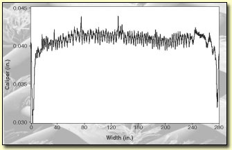
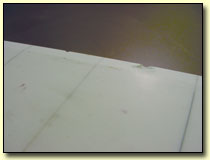
Fabric wear profiles or caliper that are performed on returned fabric strips are like the fingerprint of each machine, and they will clearly show if changes are occurring from one fabric run to another. Also, as demonstrated in Figure 1, they can clearly identify problem areas requiring attention and provide the exact location across the fabric width if the sample edges are identified.
|
| Figure 1. Used fabric wear profile illustrating both edge and periodic wear |
 |
|
This example clearly shows a severe deckle region wear problem very close to both fabric edges and a regularly spaced wear problem across most of the fabric width. In this example, the mill should examine the condition of all suction box deckle strips, and if no problems are detected, it should consider staggering the deckle positions and changing to lubricated deckles to reduce the wear rate at the edges. When given an exact measurement of the periodic spacing of the lines of wear across the machine width, the mill can readily identify the offending component(s) that have the same spacing and rectify the problem. This is most likely caused by shifting ceramic tiles.
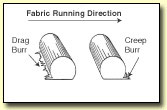
Creep wear burrs are forward-facing burrs where the wear debris from the fabric strands is sticking to the front or leading edge of the strands (Figure 2). These creep burrs can only be caused by a surface that is moving faster than the fabric can and sweeping its wear debris ahead of the fabric run. Creep wear is most often caused by rolls with abrasive surfaces.
|
| Figure 2. Cross-machine direction strands with creep and drag wear burring |
 |
|
The most frequent causes of creep wear are under- or over-crowning of a roll, the deflection of weak rolls causing a reduction in fabric path length in the middle of the machine, and random bands of dirt buildup on poorly doctored rolls. Fabric wear due to roll problems can occur on both the machine and paper sides of the fabric. It should be noted that the wear often extends to the very outside edges of the fabric.
One special cause of creep wear across the full fabric width can be at the driven rolls. Because fabrics are elastic, the cumulative drag load will stretch them to the highest tension ahead of the first drive roll. Then, they will shrink back on the drive roll surfaces as they relax to their lowest tension after the drive rolls. If any drive roll surface is abrasive, then severe creep wear will occur as the fabric continually creeps or moves backward on the drive roll surface.
In fairly rare instances, a very localized full-width CD band of creep burrs can occur when there is a complete loss of traction by a driven roll, and the roll spins out of control inside the fabric.
Drag or trailing wear burrs in the opposite direction to the creep burrs are frequently caused by abrasive stationary drainage elements that drag the wear debris backward against the run direction. In typical drag wear cases, the wear frequently does not run to the extreme edges of the fabric but stops in the sheet deckle region. The edges of the stationary ceramic drainage elements can become rough or sharp with time as wear removes the original polished radius that was supplied. Fabric life can often be improved by restoring the original edge quality or even replacing severely worn elements with a better-quality ceramic.
It should be remembered, however, that roll surfaces traveling slightly slower than the fabric can also cause drag wear. This occurs when there are roll bearing problems or the roll diameter is locally reduced by wear, corrosion, and all the same problems that cause other regions of the roll surface to run faster. When the drag wear is caused by roll problems, the wear frequently runs out to the extreme edges of the fabric.
The surface quality of the worn strand surfaces provides excellent clues as to the coarseness of the wearing surface. A very smooth, worn surface points to a fine but severe abrasive such as mineral fillers added to the furnish for opacity. This condition should not be confused with the deliberate surfacing of the fabric that clothing suppliers sometimes perform to improve the fabric topography on the machine side for better guiding or to reduce undesirable sheet marking by out-of-plane paper side strands.
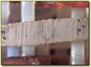
An almost random but roughly worn surface, as shown in Figure 3, is more typical for roll surface problems such as corrosion or a deteriorated roll covering.
|
| Figure 3. A roughly worn fabric surface is typical of abrasive roll problems. |
 |
|
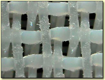
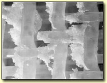
The more uniformly rough surfaces shown in Figure 4 indicate a scratching action that is symptomatic of uneven drainage surfaces.
|
| Figure 4. A uniformly rough scratchy fabric surface is typical of uneven drainage surfaces. |
 |
|
Localized drag scoring is distinguished by narrow bands of wear or gouging around the fabric length. These may sometimes be so narrow as to cut into part of an individual wear strand surface, leaving a line of wear around the full length of the fabric. The damage is similar to that shown in Figure 4, but the gouging is more localized and severe. Often, the natural oscillation of the fabric between the guide palms will produce an even wider band of wear than the actual width of the offending edge.
Typical scoring sources can be as simple as a single grain of sand or rust stuck in a foil blade surface. Another common cause of scoring damage is uneven segmented ceramic surfaces that have shifted position or a chipped ceramic doctoring edge, such as on a lead-forming board blade.
The nose chipping of the fragile doctoring edges on ceramic blades is almost impossible to avoid without extreme care at all times. This form of ceramic damage, shown in Figure 5, is also very likely to show up as a sheet formation streak. The defect on the left blade is small enough to be honed to a gentle radius with a diamond tool to remove potential fabric cutting edges. Replacement or regrinding may still be required for the right blade’s defect if it still shows as a formation mark in the sheet.
|
| Figure 5. Two adjacent ceramic tiles with chipped doctoring edges |
 |
|
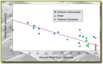
ABRASIVE FILLERS. Mineral fillers are hard abrasive materials that can severely reduce fabric life if they get between the fabric and the machine surfaces. Maintaining a high first-pass filler retention is the most effective way to reduce fabric wear because it keeps the abrasive fillers in the sheet and out of the constantly recirculating white water system.
As Figure 6 shows, the abrasiveness of most fillers on fabrics is roughly proportional to particle size. Finer particle sizes are preferred for fabric life, and coarse fillers are to be avoided.
|
| Figure 6. Effect of filler particle size on fabric wear |
 |
|
FABRIC MELTING. Over the years, there have always been occasional incidents of forming fabric destruction by melting, as shown in Figure 7. These incidents are becoming increasingly more commonplace for a number of reasons. In particular, some hybrid top former drainage units have raised sheet consistencies to unexpectedly high values and reduced the need for a large number of flat boxes or high vacuum boxes (hivacs) between the hybrid unit and the couch roll.
|
| Figure 7. Fabric melt debris blocking mesh |
 |
|
In recent years, there has also been tremendous progress in drainage optimization of the wet end to deliver the driest possible sheet at the lowest drag load into the press section. The number and size of hivacs have been reduced and the available vacuum capacity redistributed on the remaining hivacs to achieve even higher vacuum levels. The old inefficient "wet suction boxes" have also been replaced by more efficient low vacuum units, and steam hoods have been added to many hivac sections to further improve dewatering. The result of all this progress is to reduce the remaining water in the sheet for removal by the last hivacs. In most situations, with correctly ascending vacuum schedules, there is just enough drained water to lubricate the forming fabric and mating hivac surfaces, but often there is not a great safety margin.
Considerable heat is generated by the frictional rubbing of the fabric on the hivac surfaces. For a typical 300-in.-wide paper machine running at 3,000 fpm with a reasonable 5-pli drag load on the last hivac, this frictional heating produces 102kW of heat at the rubbing surfaces or the equivalent of more than one thousand 100-watt light bulbs. This heat can only be conducted away either through the hivac, by the vacuum airflow, the traveling fabric surface, or the drained white water. The heat dissipation is essential to prevent the excessive surface temperatures that can damage the hivacs and melt forming fabrics.
The drained white water is even more important than the other three heat conductors are, as it provides the lubrication of the rubbing surfaces. Without this critical lubrication, the drag load on the hivac will often triple and turn what was a risky situation into a damaging one.
On several paper machines, there have been instances of poorly lubricated fabrics stretching off the machine. They were then packed and returned whole to the supplier, who discovered that the length had returned to the correct minimum length for that machine.
Wet end drainage audits with a gamma gauge can be used to determine the drainage at each hivac when spacing between units permits. Although it is difficult to exactly predict the drainage levels that will cause melt problems for every situation, there are many instances where zero drainage is reported, and these must always be corrected without delay. A steeply ascending hivac vacuum schedule is essential and should be the first step in correcting the problem. It may also be necessary to adjust the vacuum level in units before or after those in trouble to maintain an ascending vacuum schedule. It may even be necessary to divert vacuum cfm capacity from other units with a surplus to where it is most needed.
If vacuum schedule adjustments and cfm diversion cannot correct the problem, then the number of hivacs must be reduced until lubrication is guaranteed on all remaining surfaces. Since the only justification for a flat-surface hivac is to provide drainage, it has no purpose if water cannot be drained. At a very minimum, it should be lowered away from the wire and preferably removed from the machine. It only adds to drive power and reduces fabric life if no drainage occurs.
Curved transfer box covers are a particular problem since they also serve an important sheet transfer function. Therefore, neighboring units should be adjusted to accommodate them. Lubrication showers at stock temperature may also be required for sheet breaks since curved covers generate frictional heat even when there is no sheet or applied vacuum. Since no drainage or lubrication occurs outside the sheet edges on curved covers, the individual deckles may need to have additional water lubrication to preserve the fabric edges.
Surface overheating due to lack of lubrication is also a problem for the fragile ceramics because a ceramic that overheats is very susceptible to thermal shock damage if suddenly cooled by cold water washups during sheet breaks. The ceramic surfaces should be dye checked for cracks that can prematurely wear the fabrics and can eventually release many ceramic fragments to permanently damage other surfaces.
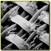
HIGH-PRESSURE SHOWER DAMAGE. The small-diameter strands used in forming fabrics are very vulnerable to fatigue damage from excessive showering. The mesh blockage that is often caused by the fibrillation of the fabric strands shown in Figure 8 reduces drainage, worsens sheet release, and sometimes marks the sheet.
|
| Figure 8. The surface of the monofilament strands are broken into fibrils, which are then pushed into the mesh openings by the shower. |
 |
|
Uniform shower damage across the full width of the fabric is a sign of excessive showering, and the shower pressure and or the nozzle distance from the fabric should be reduced.
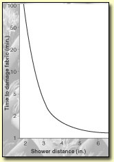
As shown in Figure 9, the exposure time required to damage the fabric can be increased tenfold by moving the shower nozzles from 4 in. to only 2.5 in. from the fabric. This result, which is contrary to intuition, is because the water jet is breaking up into water droplets after leaving the nozzle, and these cause more vibrating fatigue damage to the strands.
|
| Figure 9. Effect of shower-to-fabric distance on the time required to damage the fabric |
 |
|
Fabric damage is always reduced by lower pressures. Therefore, showers should always be run at the lowest pressure that gives adequate cleaning. It should be noted that the lower pressures that are typically used for flooding nip showers are perfectly adequate for keeping the fabric very clean.
Regular machine direction lines of shower damage spread across the full width of the fabric at the same spacing as the shower nozzles can indicate a failed reciprocator or one that dwells for too long at the ends of the stroke. Any slight hesitation at either end of the oscillator stroke will greatly increase the local exposure times in those machine direction lines in the fabric.
Random bands across the width that can be related to multiples of the nozzle centers may mean that several nozzles are worn, oversized, or, in the case of fan nozzles, that some are behaving like the more damaging needle jets due to contamination.
Damage that occurs only to the seam area can sometimes be solved by minimum showering conditions because the seam area is usually the most vulnerable part of the fabric. In those instances where damage cannot be eliminated, a more damage-resistant seam design can often be supplied, and the fabric can also be woven using more damage-resistant strand materials.
| RECOMMENDED STEPS FOR EXTENDING FABRIC LIFE |
|
1. Cut a full-width strip from the used fabric, and clearly identify fabric and direction of run.
2. Obtain a detailed used fabric analysis from the clothing supplier.
3. Track changes and trends in reported fabric problems.
4. Correlate these wear rate changes with maintenance records.
5. Carefully inspect machine surfaces that are suspect and rectify identified problems.
6. Seek expert advice where required
|
RICHARD PITT is team leader APD, equipment for AstenJohnson in Kanata, Ont.
A version of this article was presented at the 2002 TAPPI Wet End Operations Short Course in Orlando, Fla.
|